3.2.2. Digitizing Wastewater Structures
3.2.2.1. General
QGEP has a wizard to correctly collect manholes and special structures. see the The QGEP wizard chapter.
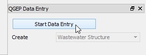
Select the Wizard button, then click Start Data Entry and choose Wastewater Structure in the pull down menu.
3.2.2.2. Digitizing
Now the cursor changes to the digitizing symbol and you can select the location of the new point element.
Then the vw_qgep_wastewater_structure form opens and you can start adding data in the General tab:
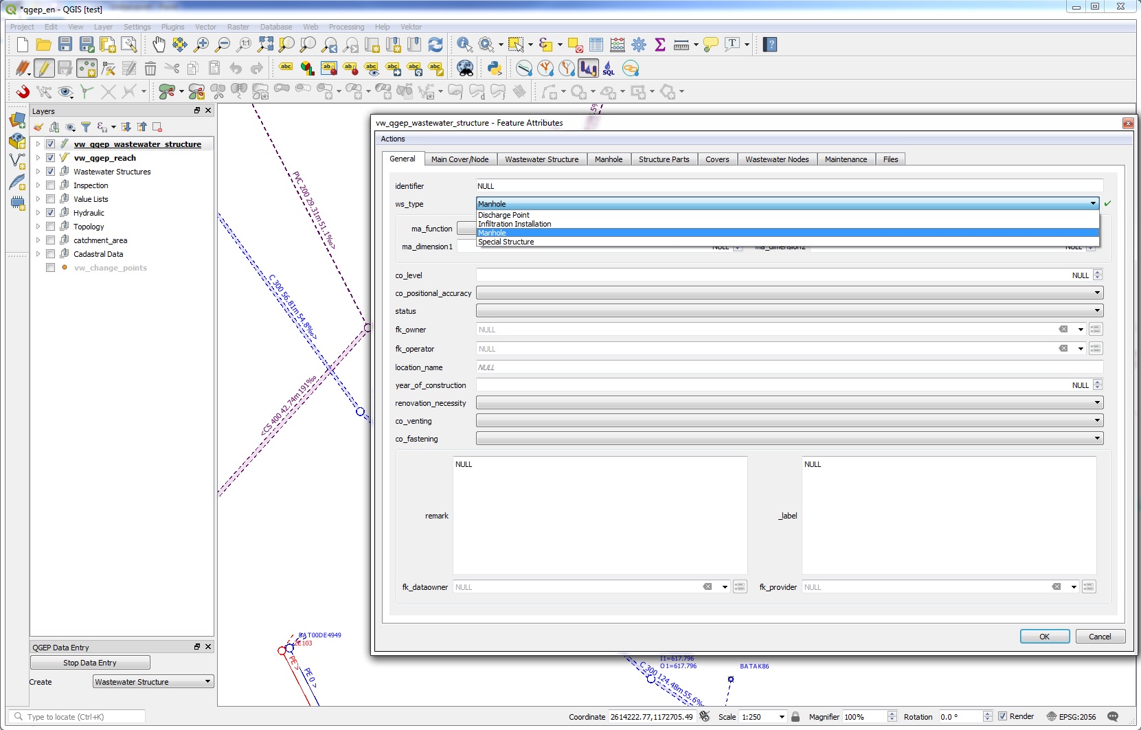
Select the ws_type you want (preselected is ‘manhole’):
manhole
special_structure
discharge_point
infiltration_installation
Depending on the ws_type, you will have different fields and tabs in the form.
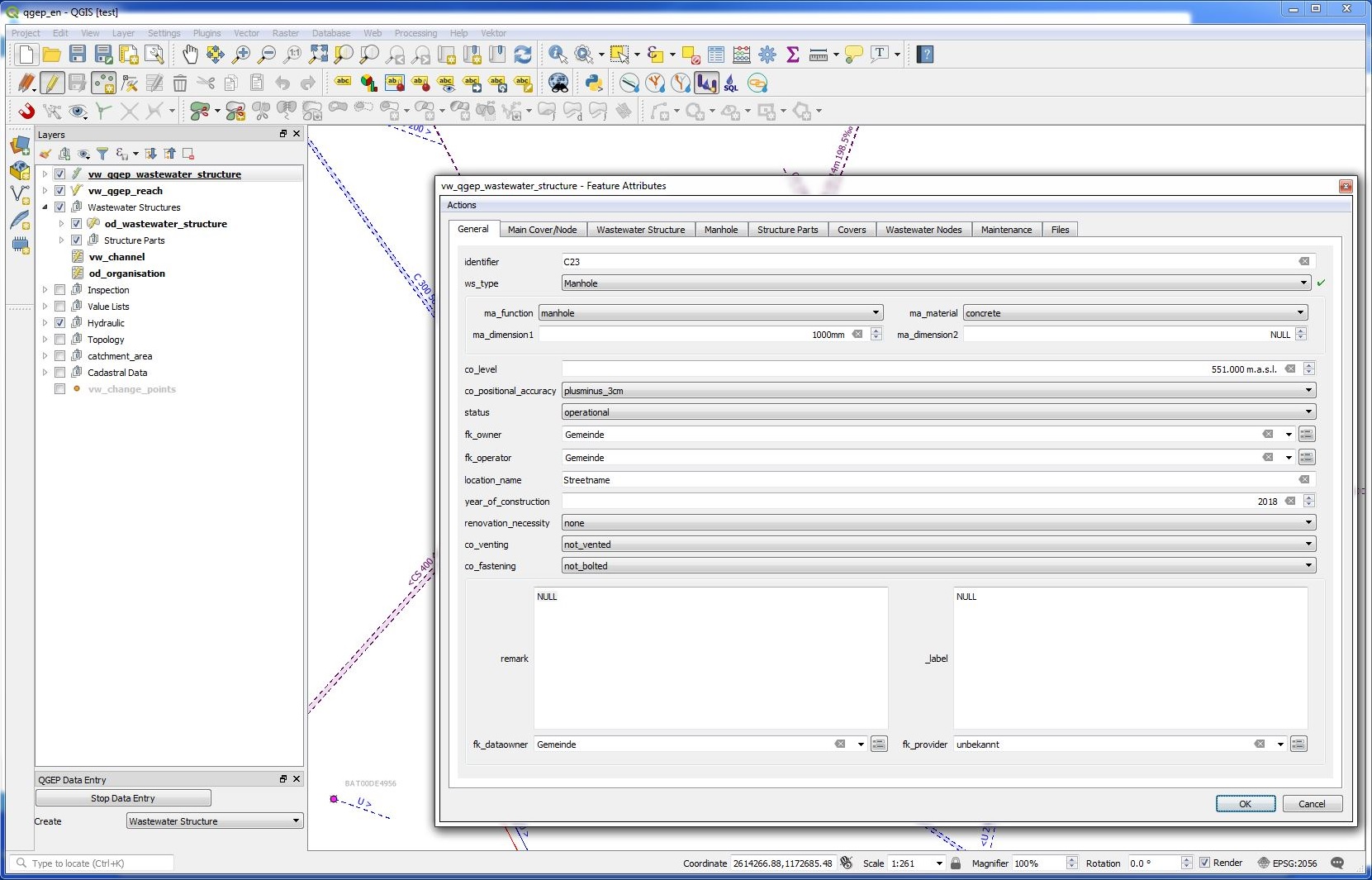
Then add the identifier (this is the attribute that will be displayed on the map).
Note
If you do not enter an identifier, QGEP will enter the obj_id also as identifier (you can change later). As default, the identifier of the wastewater structure is also the identifier of the cover and of the wastewater node.
Add other attributes in the General tab. You can also add attributes in the other tabs (Cover, Wastewater Structure, Manhole, WasteWater Node).
Note
The idea of the General tab is, that in the normal digitizing process (95% of the manholes) the user has not to change the tabs to enter the attributes that are necessary.
Attention
You can not add new records in the tabs Covers, Structure Parts, Wastewater Nodes and Maintenance, because you have to save first the Wastewater Structure-record to the database before you can add additional records. You can not use Actions for the same reason. First safe the record.
Click OK to close the form.
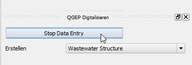
Save the information of this layer by stopping the data entry wizard.
You can re-edit your point object selecting the edit mode and then click with the info cursor on the object you want to edit. If you do not select the edit mode, you can just look at the existing data.
For detailed information about editing see the Editing of existing data chapter.
3.2.2.3. Further attributes and classes
When a wastewater_structure object is digitized, a series of steps take place in the background in the QGIS database:
an new object in the class wastewater structure is added
a new object in the respective subclass [discharge_point, infiltration_installation, manhole, special_structure] is added and linked
a new cover object is added and linked to the wastewater structure
a new wastewater node object is generated in wastewater network elements and its subclass wastewater nodes
To add additional objects such as structure parts (besides covers there are access aids, back flow prevention etc) you have to save first and then edit the point object (see the Editing of existing data chapter).
Note
To add a second cover or a second wastewater node to a wastewater structure, see the Editing of existing data chapter.
3.2.2.4. Geometry synchronization
The added feature’s geometry defines the geometry of the connected tables like cover and wastewater node. The vw_qgep_wastewater_structure-point itself has no Z value. When the level of the cover co_level is entered, this value is adapted to the Z value of the cover’s geometry. The bottom level of the wastewater node wn_bottom_level defines the Z value of the wastewater node’s geometry.
Note
If a cover level changes, the Z value of the cover’s geometry will be adjusted. When the geometry changes, the co_level attribut is adjusted as well. If both values change, the level takes precedence. On an insert it’s like when both value change. Means the cover’s geometry is set according to the cover level and if it’s NULL, the Z value is set to NaN. The same situation is on editing the wastewater node directly.