3.2.5. Digitizing Channels
3.2.5.1. General
QGEP has a wizard to correctly build channels and connect them to wastewater structures respectively to wastewater nodes or other reaches (building up the topology for waste water nodes and reaches). See the The QGEP wizard chapter.
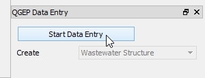
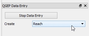
Select the Wizard button, then click Start Data Entry and choose Reach in the pull down menu.
Attention
Start digitizing in the direction of the flow by starting with the from manhole node and finishing with the to manhole node.
3.2.5.2. Digitizing
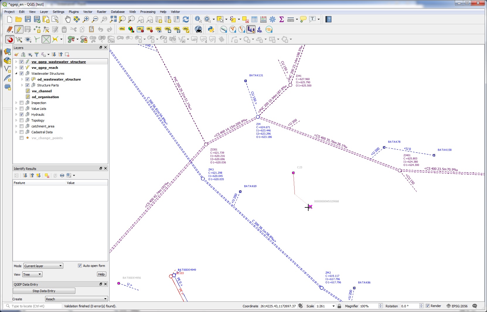
In digitizing mode the cursor will automatically snap to the nearest wastewater node or reach. When left clicking a line starts to draw.
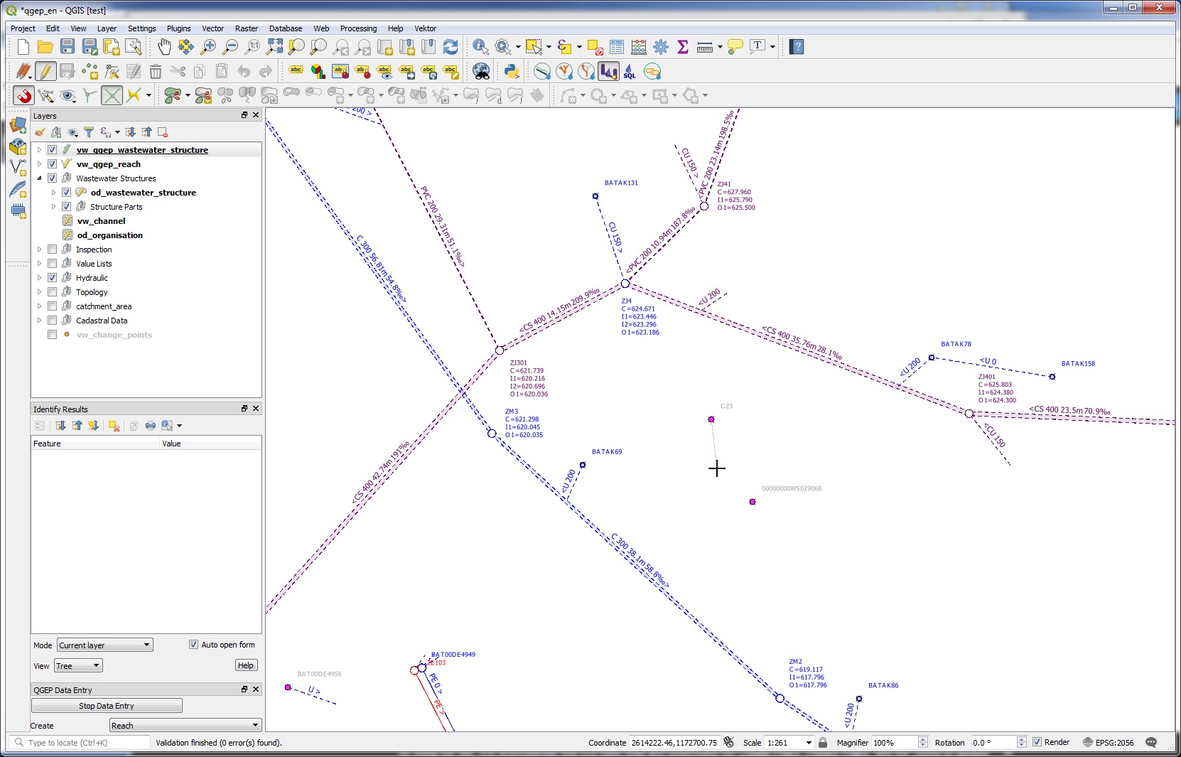
With further left clicks anywhere you can define intermediary points of the reach progression. You can also directly select another manhole to draw a straight channel.
It is possible to use the Advanced Digitizing tools together with the wizard.
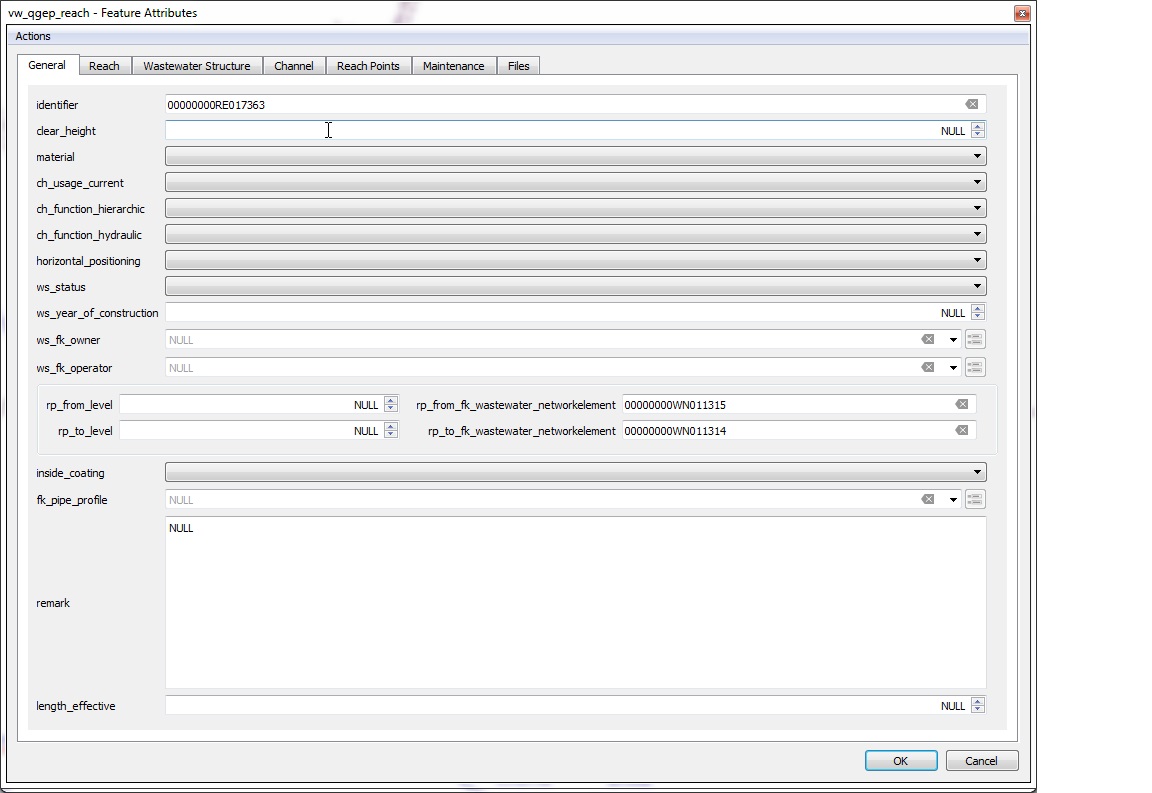
You finish digitizing the line by right clicking. This will make the vw_qep_reach form appear and you can start adding data in the General tab:
Note
Keep in mind that the finishing point of the line is the last point where you left clicked. Thus, for digitizing a simple line with 2 points you need two left clicks to digitize the line and one right click to finish the line digitizing.
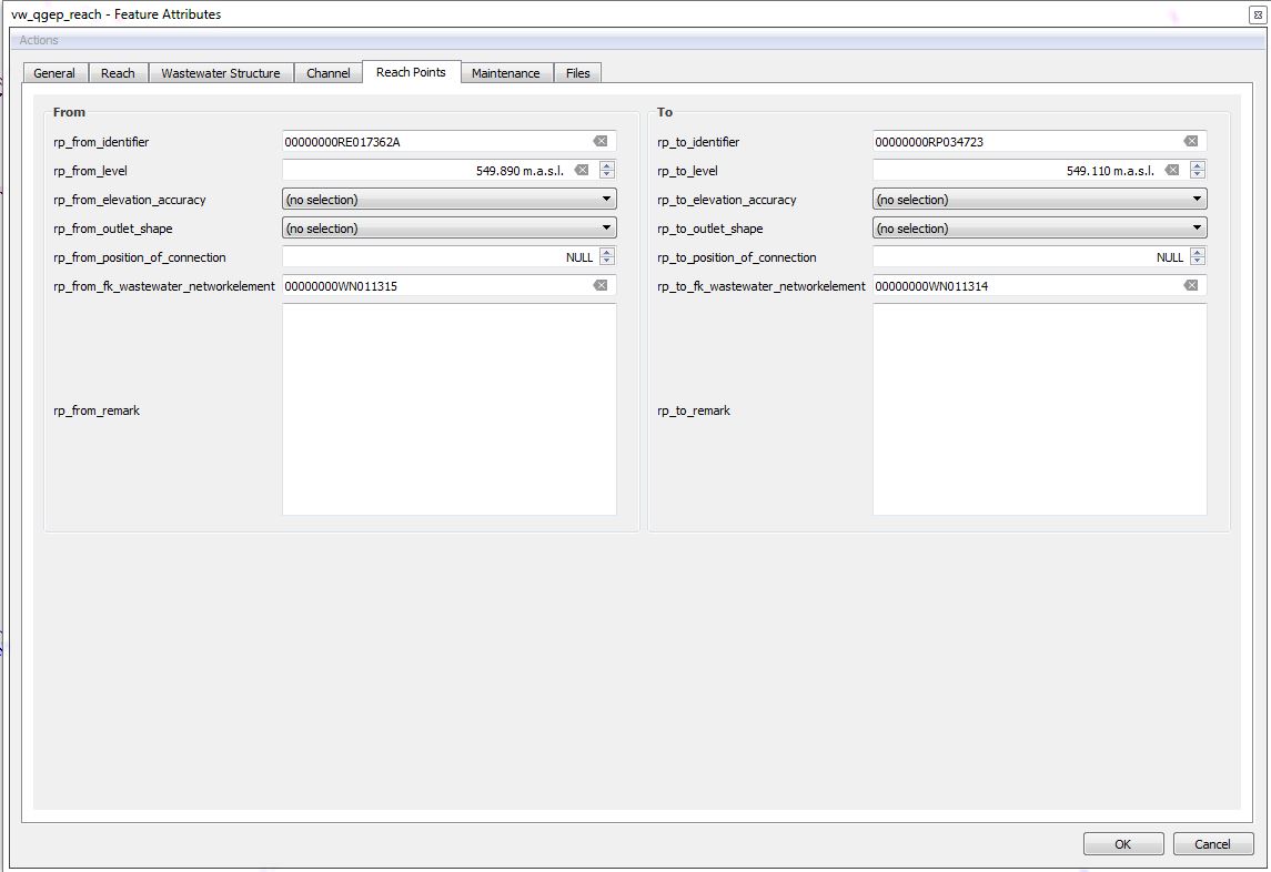
Control the snapping to wastewater nodes or other reaches in the fields rp_from/to_fk_wastewater_networkelement
Note
If you do not enter an identifier (reach-identifier) in the General tab, QGEP will enter the obj_id also as identifier (you can change later). As default, the identifier of the reach is also the ws_identifier of the channel. The reachpoint-identifier are build from the reach-identifier+’F’ or +’T’ (from- and to-reachpoint).
Note
See Geometry synchronization for automatic reachpoint levels when snapping to wastewater nodes with level.
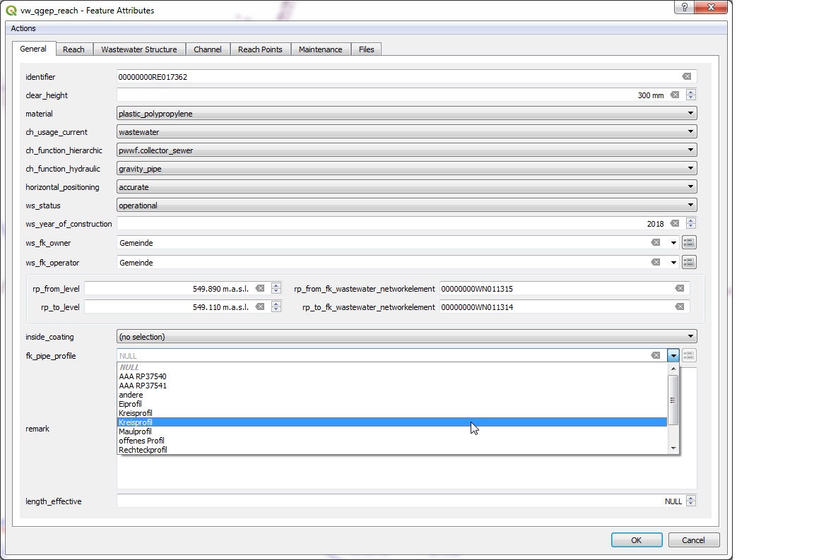
For the profile type you will get a list of defined profiles. You can edit those in od_pipe_profile table.
When finished, then click the OK button.
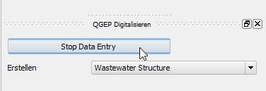
Save the information of this layer by stopping the data entry wizard.
Note
The standard-fields on the General tab (and only those fields) do reuse the last entered attribute value when you add new reaches with the wizard. The QGIS option Reuse the last entered attribute values and the default values have no influence on these fields.
You can re-edit your object selecting the edit mode and then click with the info cursor on the object you want to edit.
If you do not select the edit mode, you can just look at the existing data.
For detailed information about editing see the Editing of existing data chapter.
3.2.5.3. Further attributes and classes
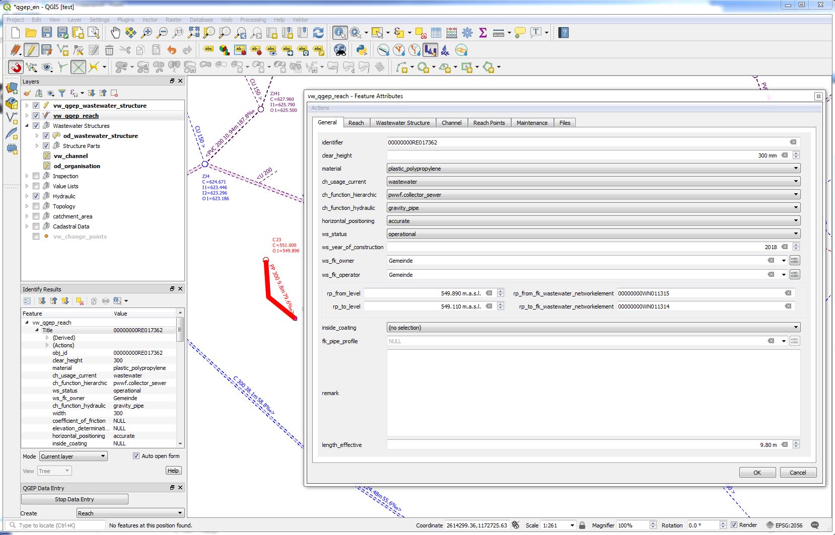
When a line object is digitized, a series of steps take place in the background in the QGEP database:
a new object is added in the wastewater structure class (
od_wastewater_structure)a new object is added and linked in the channel subclass (
od_channel)a new reach object is generated in the wastewater network elements class (
od_wastewater_networkelement) and its subclass reach (od_reach)two new reach point objects are added and linked to the reach (rp_from_node, rp_to_node)
3.2.5.4. Geometry synchronization
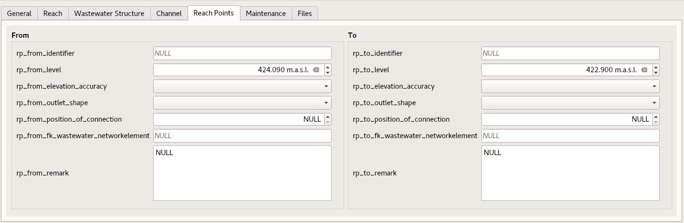
The start- and the end-point of the added feature’s geometry defines the reach point’s geometries. The altitude (Z value of geometry) of the added feature’s start- and the end-point is defined by the level values rp_from_level and rp_to_level. This means, the Z values of the reach point’s geometry is set by the level as well. These values could be filled up by the snapped features:
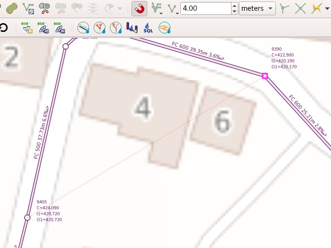
The snapped features 9405 and 9390 have the altitude from the wastewater node bottom_level. These values are copied into the attributes rp_from_level and rp_to_level and can be edited there by the user. When the user changes these values, the Z value of the geometry of the digitized feature and its reach points will be changed as well.
Note
If a reach point’s level changes, the Z value of its geometry changes, and so does the start- or the end-point of the reach. When the Z value of the reach’s geometry changes, the reach point’s geometry and its level is ajusted as well. If both values change, the level takes precendence. On an insert it’s like when both value change. Means the reach’s geometry is set according to the reach point’s levels and if they are NULL, the Z value of the reach’s start- and end-point are set to NaN.